Friday 27 October 2017

brownout and blackout

brownout

 is an intentional or unintentional drop in voltage in an electrical power supply system. Intentional brownouts are used for load reduction in an emergency. The reduction lasts for minutes or hours, as opposed to short-term voltage sag (or dip). The term brownout comes from the dimming experienced by lighting when the voltage sags. A voltage reduction may be an effect of disruption of an electrical grid, or may occasionally be imposed in an effort to reduce load and prevent a power outage known as a blackout.


blackout

 is a complete interruption of power in a given service area. Rolling blackouts are controlled and usually preplanned interruptions of service. A brownout is a partial, temporary reduction in system voltage or total system capacity. Blackouts come without warning, last for indeterminate periods, and are typically caused by catastrophic equipment failure or severe weather. The nature and cause of the blackout determines who is affected. Rolling blackouts typically occur with at least some advance warning, normally last for a fixed length of time, and are deliberately produced by utility companies. They can be used as a means of coping with peak power demands that cannot be met from existing supply.

comparing voltage spikes and power surges

Power spikes

 are very short pulses of energy on a power line and contain very high voltages. These spikes only last a few milliseconds, but they have the potential to cause great damage to sensitive equipment. Often equipment does not fail right away; however in many instances when it does, this seriously affects the shelf life of any electrical equipment.

Power surges 

 are a temporary increase in a voltage on a power line. Typically surges have less voltage than spikes, however they last much longer and sometimes can surges are preceded by spikes.

Thursday 26 October 2017

OH&S Requirement for testing electrical/ electronic equipment


OH&S regulation for the it industry

The purpose of the OHSR is to promote occupational health and safety and to protect workers and other persons present at workplaces from work-related risks to their health, safety, and well-being. Compliance with the requirements provides the basis on which workers and employers, in cooperation, can solve workplace health and safety problems. The requirements are not an end in themselves, but are a foundation upon which to build an effective health and safety program.

Type of measuring devices for testing equipment and devices

The testing equipment used to detect faults in the operation of electronic devices by creating stimulus signals and capture responses from electronic devices under test is known as electronic test equipment. If any faults are detected, then identified faults can be traced an rectified using electronic testing equipment. Most often all electrical and electronic circuits are tested and troubleshooted to detect faults or abnormal functioning.

Type of measuring devices

Voltmeters
Ohmmeter
Ammeters
Multimeters

how to test equipment

The periodic inspection and testing of portable electrical equipment is commonly known as “test and tag”. The University guideline for test and tag allows for risk assessment of a device, it’s environment and use to adjust the period between inspections. The process of physically inspecting equipment is just as important as the electrical test performed with an insulation tester and it is encouraged that all staff pay attention to their equipment for signs of physical or chemical damage. If there is any doubt as to the integrity of the device, or if there appears to be parts missing (such as guards), remove the item from service and contact an electrician.

Type of risk of not using measuring device correctly

Voltmeter
 are important because that are safety equipment.  A voltmeter with an incorrect indication increases the risk of electrocution.  If a voltmeter fails in service, an arcing fault can be the result.  In fact, many injuries do occur because of voltmeter failures.  Voltmeters are more important than some other safety devices because exposure to electrical injury exists in every instance.  Therefore, you should keep voltmeters in a safe place and protect them from damage.

Ohmmeter
Be certain the circuit is deenergized and discharged before connecting an ohmmeter. Do not apply power to a circuit while measuring resistance.

Ammeter
The low resistance ammeter makes the effective resistance of the circuit very low and so the current is very big.  The ammeter actually shorts out the component it's trying to measure the current through.
This can damage the ammeter because a very big current flows in it.
Multimeters

How to check calibration of device
Set the multimeter to the highest resistance range by turning the dial to the highest "ohm" setting. Touch the test probes of your digital multimeter together. The digital display of the multimeter should  read "0 ohms."

Reference


The University of Queensland Occupational Health & Safety Division Home Page. (n.d.). Retrieved November 22, 2017, from http://www.uq.edu.au/ohs/electrical-safety


Tuesday 24 October 2017

Testing for a Blown Fuse

Whilst it is easy to visually inspect the element in a glass fuse to see if it has blown, the majority of fuses have solid, non-transparent bodies that hide the element from view. To test if the fuse is blown, we require a multimeter. Once configured, a multimeter can measure the resistance of the fuse element. Resistance is measured in Ohms 'Ω'. The following tutorial uses a digital multimeter, however the same principles apply when using an analogue multimeter (ie. one with a needle display). If you are using an analogue meter, firstly read the tutorial and then refer to the additional notes at the end.


1. Connecting the Test Leads.

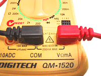
The black lead should be connected to the Common socket.
The red lead should be connected to the Ω or Ohms socket. Picture of correct connection points for leads


2. Selecting the Correct Setting.


Move the dial to the lowest range of the Ohms scale (200 ohms is the lowest setting on this mulitmeter). This should also power the meter ON. If there is a seperate ON switch, please turn the meter ON. You can see in the picture that the Ohms range is illustrated by a light green band in lower left area.

The 5 different Ohms range settings on this multimeter are;
2M = 2,000,000 ohms or 2 Megaohms (highest resistance setting)
200k = 200,000 ohms
20k = 20,000 ohms
2k = 2,000 ohms
200 = 200 ohms (lowest resistance setting) Picture of setting the meter correctly

Touch the metal tips of the 2 testing leads and whilst holding them together, the meter display should change to show that little or no resistance is present. Power will simply flow from one lead back through the other. When you seperate the two tips, the meter display will return to a 100% resistance state.

4. Measure the Fuse.

Important! Place the fuse on a non-conducting surface such as wood, laminate or plastic. Touch the metal caps at each end of the fuse with the metal tips of the testing leads. There is no polarity so you can use any lead for either fuse cap. Ensure to make good contact by touching a clean metal surface on each cap. Whilst the leads are firmly connected to the fuse, look at the reading displayed on the multimeter.

Note: If you wish to test a fuse still located in a circuit. Please ensure that you have turned off power and disconnected the power source to avoid possibility of electric shock. Picture of how to test the fuse with the testing leads

5. Understanding the Reading.

Fuse is OK: If the meter reading changes to a low resistance value (similar to the result of touching the 2 leads together).

Fuse is Blown: If the meter reading does not change and display still shows the original 100% resistance state.

Don't forget to turn the multimeter OFF when you have finished testing. Picture of different meter readings

Using multimeter to testing resistance

To begin, make sure no current is running through the circuit or component you want to test. Switch it off, unplug it from the wall, and remove any batteries. Remember that you'll be testing the resistance of the entire circuit. If you want to test an individual component such as a resistor, test it by itself—not with it soldered in place!
Plug the black probe into the COM port on your multimeter.
Plug the red probe into the VΩmA port.
Switch on your multimeter, and set the dial to resistance mode. Resistance is measured in ohms, indicated by the Ω symbol.
Most multimeters are not autoranging, meaning you will need to set the correct range for the resistance you expect to measure. If you're not sure, start with the highest setting.
Place one probe at each end of the circuit or component you want to test. It doesn't matter which probe goes where; resistance is non-directional. If your multimeter reads close to zero, the range is set too high for a good measurement. Turn the dial to a lower setting.
If you set the range too low, the multimeter simply reads 1 or OL, indicating that it is overloaded or out of range. This won't hurt the multimeter, but we need to set the dial to a higher range. The other possibility is that the circuit or component you are testing doesn't have continuity—that is, it has infinite resistance. A non continuous circuit will always read 1 or OL on a resistance test.
With the multimeter set to a usable range, we get a reading of 1.04k ohms.

using multimeter to test voltage

Testing Voltage
Plug the black probe into the COM port on your multimeter.
Plug the red probe into the VΩmA port.
Switch on your multimeter, and set the dial to DC voltage mode (indicated by a V with a straight line, or the symbol ⎓). Virtually all consumer electronic devices run on DC voltage. AC voltage—the kind that runs through the lines to your house—is considerably more dangerous, and beyond the scope of this guide.
Most multimeters are not autoranging, meaning you will need to set the correct range for the voltage you expect to measure. Each setting on the dial lists the maximum voltage it can measure. So for example, if you expect to measure more than 2 volts but less than 20, use the 20 volt setting. If you're not sure, start with the highest setting.
Place the red probe on the positive terminal, and the black probe on the negative terminal. If your range was set too high, you may not get a very accurate reading. Here the multimeter reads 9 volts. That's fine, but we can turn the dial to a lower range to get a better reading.
If you set the range too low, the multimeter simply reads 1 or OL, indicating that it is overloaded or out of range. This won't hurt the multimeter, but we need to set the dial to a higher range.
With the range set correctly, we get a reading of 9.42 volts.
Reversing the probes won't do any harm; it just gives us a negative reading.

Perform housekeeping duties

the requirements of housekeeping The word “housekeeping” can interpret cleaning floors and surfaces, removing dust, and organizing clutter...